MOTOR-DRIVER PCB LAYOUT GUIDELINES (PART 1)
In Part 1, we’ll discuss some general recommendations for designing PCBs that use motor-driver ICs, which require special cooling techniques to handle the power dissipation.
Printed-circuit-board (PCB) substrate material, like FR-4 glass epoxy, is a poor conductor of heat. Conversely, copper is an excellent conductor of heat. So, more copper area on a PCB is ideal from a thermal-management perspective.
Thick copper, like 2-oz. foil (68 microns thick), conducts heat better than thinner copper. Unfortunately, using thick copper is expensive, and makes it difficult to achieve fine geometries. Therefore, the use of 1-oz. (34 microns) copper has become commonplace. For external layers, this is often ½-oz. copper plated up to 1-oz. thickness.
Solid-copper planes used on inner layers of multi-layer boards work well to spread heat. However, since these planes are normally placed in the center of the board stack-up, the heat can get trapped inside the board. Adding copper areas on the outer layers of the PCB and placing many vias to connect, or “stitch,” these areas to the inner planes helps transfer heat out of the planes.
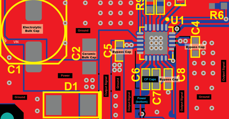
On two-layer PCBs, spreading heat may prove more difficult due to the presence of traces and components. Providing as much solid copper as possible with good thermal connections to the motor-driver IC is a necessity. Putting copper pours on both outer layers and stitching them together with many vias helps spread the heat across areas cut by traces and components.